


Next: X-ray Diffraction
Up: Chain of sources
Previous: Phased array
Contents
Figure 12.12:
Diffraction
grating
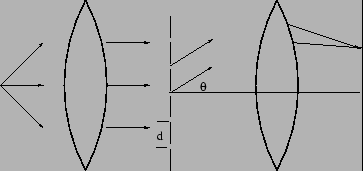 |
We consider the transmission diffraction grading shown in
Figure 12.12. The transmission grating is essentially
a periodic arrangement of  slits, each slit of width
  and
slit spacing
and
slit spacing  . The spacing between successive slits is
referred to as the ``grating element'' or as the ``period of the
grating". Each slit acts like a source, and the diffraction
grating is equivalent to the chain of sources shown in
Figure 12.10.
. The spacing between successive slits is
referred to as the ``grating element'' or as the ``period of the
grating". Each slit acts like a source, and the diffraction
grating is equivalent to the chain of sources shown in
Figure 12.10.
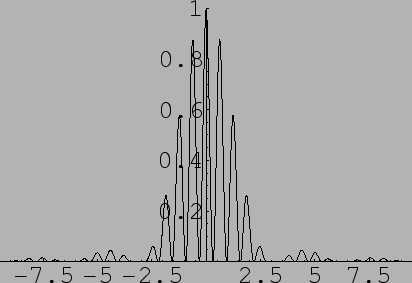
The intensity pattern of a diffraction grating is the product of the
intensity pattern of a single slit and the intensity pattern of a
periodic arrangement of emmiters
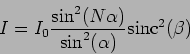 |
(12.28) |
where
Typically the slit spacing is larger than the slit width ie. .
Figure 12.13 shows the intensity pattern for a
diffraction grating.
The finite slit width causes the higher order primary
maximas to be considerably fainter than the low order ones.
Figure 12.13:
Intensity pattern
of a diffraction grating
|
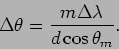
The transmission grading is a very useful device in spectroscopy.
The grating is very effective in dispersing the light into
different wavelength components. For each wavelength the  th
order primary maximum occurs at a different angle determined by
th
order primary maximum occurs at a different angle determined by
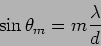 |
(12.29) |
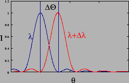
The diffraction pattern, when two different wavelengths are
incident on a grating, is shown in the Figure 12.14.
Figure 12.14:
Diffraction pattern for two wavelengths (Intensity vs
 )
)
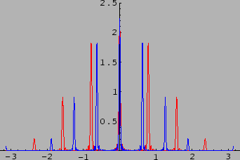 |
The dispersive power of a grating is defined as
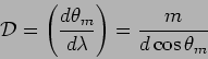 |
(12.30) |
We see that it increases with the order and is inversely
proportional to . The finer the grating (small ) the more
its dispersive power. Also, the higher orders have a greater
dispersive power, but the intensity of these maxima is also
fainter.
Figure 12.15:
Chromatic
resolution
 |
The Chromatic Resolving Power(CRP) quantifies the ability of a
grating to resolve two spectral lines of wavelengths  and
and
 . Applying Rayleigh's criterion, it will
be possible to resolve the lines if the maximum of one coincides
with the minimum of the other.
. Applying Rayleigh's criterion, it will
be possible to resolve the lines if the maximum of one coincides
with the minimum of the other.
The minimum corresponding to
(Figure 12.15) is at
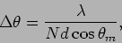 |
(12.31) |
from the maximum and the maximum corresponding to
is at
 |
(12.32) |
Equating these gives the CRP to be
 |
(12.33) |
The chromatic resolving power increases with the number of surfs
or rulings in the grating. This makes the grating a very powerful
dispersive element in spectrometers.
Problems
- For a slit of dimensions
 ,
what are the positions of the first three minima's on either side of
the central maxima? Use
,
what are the positions of the first three minima's on either side of
the central maxima? Use
 and
and
 .
.
- For a rectangular slit whose whose smaller dimension is ,
what are the positions of the maxima for light of wavelength
? (Ans.
 ,
,  ,
,  , etc.)
- Calculate the ratio of intensities of the first intensity
maximum and central maximum for the previous problem. (Ans.
 21)
21)
- Compare the angular resolutions of two circular
apertures
a.
 and
and
b.
and
and
b.
 and
and
 .
.
- A plane wave of light with wavelength
 falls on a slit of width
at an angle
falls on a slit of width
at an angle
 to the normal. Find the angular position, with respect to
the normal, of the first minima on both sides of the central maxima.
to the normal. Find the angular position, with respect to
the normal, of the first minima on both sides of the central maxima.
- The collimator of a spectrometer has a diameter of 2cm. What
would be the largest grating element for a grating, which would
just resolve the Sodium doublet at the second order, using this
spectrometer. (Sodium doublet: nm and
 nm, Ans.
 0.04mm)
- Obtain the expression of intensity for a double slit with
separation between the slits and individual slit width , as
a special case of N=2.
- Plot intensity profile as a function of
 for a
double slit with
for a
double slit with  mm and
  mm. Assume wavelength of
the incident monochromatic light to be equal to nm. Keep
mm. Assume wavelength of
the incident monochromatic light to be equal to nm. Keep
 . Notice that there are no 4th order and
the 8th order intensity maxima in the above. These are called the
missing orders in the pattern.
. Notice that there are no 4th order and
the 8th order intensity maxima in the above. These are called the
missing orders in the pattern.
- Missing orders: Find the ratio of and for the
following double slit diffraction, Figure 12.16.
Figure 12.16:
A double
slit diffraction pattern
 |
- Find an expression for the intensity of a double slit
diffraction when one of the slits is having a width C and the
other is having a width D and the separation between them is .
Next: X-ray Diffraction
Up: Chain of sources
Previous: Phased array
Contents
Physics 1st Year
2009-01-06