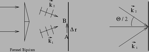
A Fresnel biprism is constructed by joining to identical thin prisms as shown in Figure 10.5. Consider a plane wave from a distant point source incident on the Fresnel biprism. The part of the wave that passes through the upper half of the biprism propagates in a slightly different direction from the part that passes through the lower half of the biprism. The light emanating from the biprism is equivalent to that from two exactly identical sources, the sources being located far away and there being a small separation between the sources. The Fresnel biprism provides a method for implementing the Young's double slit experiment.
The two waves emanating from the biprism will be coplanar and in
different directions with wave vectors ![]() and
and ![]() as shown in Figure 10.5. We are interested in the intensity
distribution on the screen shown in the figure.
Let A be a point where both waves arrive at the same phase.ie
as shown in Figure 10.5. We are interested in the intensity
distribution on the screen shown in the figure.
Let A be a point where both waves arrive at the same phase.ie
![]() ie.
ie.
![]() .
The intensity at this point will be a maximum. Next consider a point B
at a displacement
.
The intensity at this point will be a maximum. Next consider a point B
at a displacement
![]() from the point A. The
phase of the two waves are different at this point. The phase of the
first wave at the point B is given by
from the point A. The
phase of the two waves are different at this point. The phase of the
first wave at the point B is given by
| (10.13) |
| (10.14) |
| (10.15) |
| (10.16) |
| (10.17) |
The analysis presented here is another way of analysing the Young's double slit experiment. It is left to the reader to verify that eq. (10.12) and eq. (10.18) are equivalent.
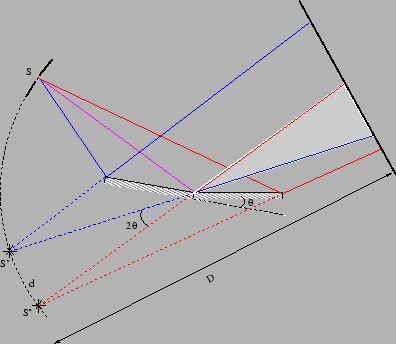
Like Fresnel biprism one can also realise double slit experiment with
`Fresnel mirrors'. Here one uses two plane mirrors and one of the mirrors is
tilted slightly (
![]() ) and glued with the other as shown in Figure
10.6.
) and glued with the other as shown in Figure
10.6.
![\begin{displaymath}
I(\Delta \vec{r})=2 I_1 \left[ 1 + \cos \left( \frac{2 \pi \theta \,
\Delta y}{\lambda} \right) \right]\,.
\end{displaymath}](img794.png)