


Next: Coherence
Up: Interference.
Previous: A different method of
Contents
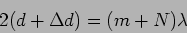
Figure 10.7 shows a typical Michelson interferometer
setup. A ground glass plate G is illuminated by a light source. The
ground glass plate has the property that it scatters the incident
light into all directions. Each point on the ground glass plate acts
like a source that emits light in all directions.
Figure 10.7:
Michelson Interferometer
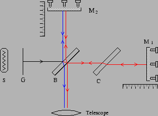 |
The light scattered forward by G is incident on a beam splitter B
which is at  .
The beam splitter is essentially a glass slab with
the lower surface semi-silvered to increase its reflectivity.
It splits the
incident wave into two parts
.
The beam splitter is essentially a glass slab with
the lower surface semi-silvered to increase its reflectivity.
It splits the
incident wave into two parts  and
and  , one which is
transmitted () and another () which is reflected. The
two beams have nearly the same intensity. The transmitted wave
is reflected back to B by a mirror M
, one which is
transmitted () and another () which is reflected. The
two beams have nearly the same intensity. The transmitted wave
is reflected back to B by a mirror M . and
a part of it is reflected into the telescope T. The reflected wave
travels in a perpendicular direction. The mirror M
. and
a part of it is reflected into the telescope T. The reflected wave
travels in a perpendicular direction. The mirror M reflects this back to B where a part of it is transmitted into T.
Figure 10.8:
Effective set-up for Michelson Interferometer
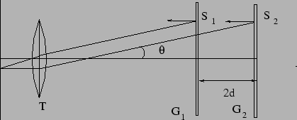 |
An observer at T would see two images of G, namely G and G
(shown in Figure 10.8) produced by the two mirrors M
and M respectively. The two images are at a separation  where
where
 is the difference in the optical paths from B to G and from B
to G. Note that traverses the thickness of the beam
splitter thrice whereas traverses the beam splitter only
once. This introduces an extra optical path for even when
M and M are at the same radiation distance from B. It is possible to
compensate for this by introducing an extra displacement in M,
but this would not serve to compensate for the extra path over a range
of frequencies as the refractive index of the glass in B is frequency
dependent. A compensator C, which is a glass block identical to B
(without the silver coating) , is introduced along the path to M
to compensate for this.
is the difference in the optical paths from B to G and from B
to G. Note that traverses the thickness of the beam
splitter thrice whereas traverses the beam splitter only
once. This introduces an extra optical path for even when
M and M are at the same radiation distance from B. It is possible to
compensate for this by introducing an extra displacement in M,
but this would not serve to compensate for the extra path over a range
of frequencies as the refractive index of the glass in B is frequency
dependent. A compensator C, which is a glass block identical to B
(without the silver coating) , is introduced along the path to M
to compensate for this.
S and S are the two images of the same point S on the ground
glass plate. Each point on the ground glass plate acts as a source emitting
radiation in all directions. Thus S and S are coherent
sources which emit radiation in all direction. Consider the wave emitted
at an angle  as shown in Figure 10.8. The
telescope focuses both waves to the same point. The resultant electric
field is
as shown in Figure 10.8. The
telescope focuses both waves to the same point. The resultant electric
field is
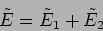 |
(10.19) |
and the intensity is
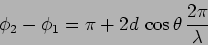
The phase difference arises because of the path difference in the two
arms of the interferometer. Further, there is an additional phase
difference of
 because undergoes internal reflection at B whereas
undergoes external reflection. We then have
because undergoes internal reflection at B whereas
undergoes external reflection. We then have
 |
(10.21) |
So we have the condition
 |
(10.22) |
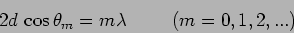
for a minima or a dark fringe. Here  is the order of the fringe,
and
is the order of the fringe,
and  is the angle of the
  order fringe.
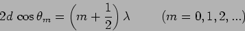
Similarly, we have
order fringe.
Similarly, we have
 |
(10.23) |
as the condition for a bight fringe.
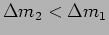
The fringes will be circular as shown in Figure 10.9.
When the central fringe is dark, the order of the fringe is
 |
(10.24) |
Figure 10.9:
Michelson fringes
|
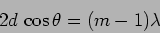
Le us follow a fringe of a fixed order, say , as we increase the
difference in the length of the two arms. The value of
 has to decrease which implies that increases. As
is increased, new fringes appear at the center, and the existing
fringes move outwards and finally move out of the field of view.
For any value of , the central fringe has the largest value of ,
and the value of decreases outwards from the center.
has to decrease which implies that increases. As
is increased, new fringes appear at the center, and the existing
fringes move outwards and finally move out of the field of view.
For any value of , the central fringe has the largest value of ,
and the value of decreases outwards from the center.
Considering the situation where there is a central dark fringe as
shown in the left of Figure 10.9, let us estimate the
radius of the first dark fringe. The central dark fringe satisfies the
condition
 |
(10.25) |
and the first dark fringe satisfies
 |
(10.26) |
For small ie.  we can write
eq. (10.26) as
we can write
eq. (10.26) as
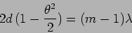 |
(10.27) |
which with eq. (10.25) gives
 |
(10.28) |
Compare this with the Young's double slit where the fringe separation
is  .
.
The Michelson interferometer can be used to determine the wavelength
of light. Consider a situation where we initially have a dark fringe
at the center. This satisfies the condition given by
eq. 10.25 where  , and are all unknown. One
of the mirrors is next moved so as to increase the difference in
the lengths of the two arms of the interferometer. As the mirror is
moved, the central dark fringe expands and moves out while a bright
fringe appears at the center.
A dark fringe reappears at the center if the mirror is
moved further. The mirror is moved a distance
, and are all unknown. One
of the mirrors is next moved so as to increase the difference in
the lengths of the two arms of the interferometer. As the mirror is
moved, the central dark fringe expands and moves out while a bright
fringe appears at the center.
A dark fringe reappears at the center if the mirror is
moved further. The mirror is moved a distance  so that
  new dark fringes appear at the center. Although initially and
were unknown for the central dark fringe, it
is known that finally the difference in lengths is
new dark fringes appear at the center. Although initially and
were unknown for the central dark fringe, it
is known that finally the difference in lengths is  and the central dark fringe is of order
  and hence it satisfies
 |
(10.29) |
Subtracting eq. 10.25 from this gives the wavelength of
light to be
 |
(10.30) |
We next consider a situation where there are two very close
spectral lines  and
and
 . Each wavelength will produce its own fringe pattern.
Concordance refers to the situation where the two
fringe patterns coincide at the center
. Each wavelength will produce its own fringe pattern.
Concordance refers to the situation where the two
fringe patterns coincide at the center
 |
(10.31) |
and the fringe pattern is very bright. As is increased,  and
and
 increase by different amounts with
 . When
 , the bright fringes of coincide with the dark
fringes of
and vice-versa, and
consequently the fringe pattern is washed away. The two set of fringes
are now said to be discordant.
, the bright fringes of coincide with the dark
fringes of
and vice-versa, and
consequently the fringe pattern is washed away. The two set of fringes
are now said to be discordant.
It is possible to measure
 by increasing to so that the two sets of fringes that are initially
concordant become discordant and are finally concordant again. It is
clear that if changes to
by increasing to so that the two sets of fringes that are initially
concordant become discordant and are finally concordant again. It is
clear that if changes to
 , changes to
 when the fringes are concordant again. We then
have
when the fringes are concordant again. We then
have
 |
(10.32) |
which gives
 |
(10.33) |
where on assuming that
 we have
 |
(10.34) |
The Michelson interferometer finds a variety of other application. It was
used by Michelson and Morley in 1887 to show that the speed of light
is the same in all directions. The armlength of their interferometer
was  .
Since the Earth is moving, we would expect the
speed of light to be different along the direction of the Earth's
motion. Michelson and Morley established that the speed of light does
not depend on the motion of the observer, providing a direct
experimental basis for Einstein's Special Theory of Relativity.
.
Since the Earth is moving, we would expect the
speed of light to be different along the direction of the Earth's
motion. Michelson and Morley established that the speed of light does
not depend on the motion of the observer, providing a direct
experimental basis for Einstein's Special Theory of Relativity.
Figure 10.10:
Laser Interferometer Gravitational-Wave Observatory
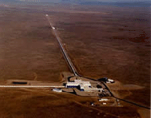 |
The fringe patter in the Michelson interferometer is very sensitive to
changes in the mirror positions, and it can be used to measure very
small
displacements of the mirrors. A Michelson interferometer whose arms
are  long (Figure 10.10) is being used in an
experiment called
Laser Interferometer Gravitational-Wave Observatory
(LIGO10.1) which
is an ongoing effort to detect Gravitational Waves, one of the
predictions of Einstein's General Theory of Relativity.
Gravitational waves are disturbances in space-time that propagate at
the speed of light. A gravitational wave that passes through the
Michelson interferometer will produce displacements in the mirrors
and these will cause changes in the fringe pattern. These
displacements are predicted to be extremely small. LIGO is sensitive
enough to detect displacements of the order of
long (Figure 10.10) is being used in an
experiment called
Laser Interferometer Gravitational-Wave Observatory
(LIGO10.1) which
is an ongoing effort to detect Gravitational Waves, one of the
predictions of Einstein's General Theory of Relativity.
Gravitational waves are disturbances in space-time that propagate at
the speed of light. A gravitational wave that passes through the
Michelson interferometer will produce displacements in the mirrors
and these will cause changes in the fringe pattern. These
displacements are predicted to be extremely small. LIGO is sensitive
enough to detect displacements of the order of
 in the mirror positions.
Problems
- An electromagnetic plane wave with
 is normally
incident on a screen with two slits with spacing
is normally
incident on a screen with two slits with spacing
 .
.
- a.
- How many maxima will be seen, at what angles to the normal?
- b.
- Consider the situation where the wave is incident at
 to the normal.
- Two radio antennas separated by a distance
 emit the same signal at frequency
  with phase difference
 . Determine the values of and so that the radiation
intensity is maximum in one direction along the line joining the two
antennas while it is minimum along exactly the opposite direction.
How do the maxima and minima shift of is reduced to half
the earlier value?
. Determine the values of and so that the radiation
intensity is maximum in one direction along the line joining the two
antennas while it is minimum along exactly the opposite direction.
How do the maxima and minima shift of is reduced to half
the earlier value?
- A lens of diameter
 and focal length
 is cut into two identical halves. A layer
  in
thickness is cut from each half and the two lenses joined again. The
lens is illuminated by a point source located at the focus and a
fringe pattern is observed on a screen
in
thickness is cut from each half and the two lenses joined again. The
lens is illuminated by a point source located at the focus and a
fringe pattern is observed on a screen
 away. What is
the fringe spacing and the maximum number of fringes that will be
observed?
away. What is
the fringe spacing and the maximum number of fringes that will be
observed?
- Two coherent monochromatic point sources are separated by a small distance,
find the shape of the fringes observed on the screen when,
a) the screen is at one side of the sources and normal to the screen is
along the line joining the two sources and b) when the normal to the screen is
perpendicular to the line joining the sources.
- The radiation from two very distant sources A and B shown in
the Figure 10.11
is measured by the two antennas 1 and 2 also shown in the
figure. The antennas operate at a wavelength . The
antennas produce voltage outputs
 and
and  which have the same phase and amplitude as the
electric field and incident on the
respective antennas. The voltages from the two antennas are
combined
which have the same phase and amplitude as the
electric field and incident on the
respective antennas. The voltages from the two antennas are
combined
and applied to a
resistance. The average power  dissipated across the resistance
is measured. In this problem you can assume that (in
radians).
dissipated across the resistance
is measured. In this problem you can assume that (in
radians).
Figure 10.11:
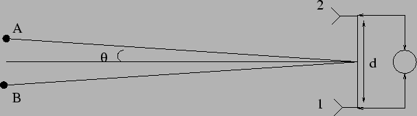 |
- a.
- What is the minimum value of (separation between the two
antennas) at which
 ?
?
- b.
- Consider a situation when an extra phase is
introduced in before the signals are combined. For
what value of is independent of ?
- Lloyd's mirror: This is one of the realisations of Young's double slit
in the laboratory. Find the condition for a dark fringe at P on the screen
from the Figure 10.12. Also find the number of fringes observed on the
screen. Assume source wavelength to be .
Figure 10.12:
Lloyd's mirror
|
- Calculate the separation between the secondary sources if the primary source
is placed at a distance
 from the mirror-joint and the tilt angle is .
- Two coherent plane waves with wave vectors
and
![$\vec{k}_1=k [\sin 30^{\circ}
\hat{i} + \cos 30^{\circ} \hat{j}]$](img857.png) with
with
 are incident on a screen which is perpendicular to the
  axis to produce straight line fringes. Determine the spacing between
two successive dark lines in the fringe pattern.
axis to produce straight line fringes. Determine the spacing between
two successive dark lines in the fringe pattern.
- Starting from a central dark fringe, eigth successive bright and
dark fringes are are observed at the center when one of the mirrors
of a Michelson interferometer
is moved
 . Determine the wavelength of the
light which is being used. (5.5 A)
. Determine the wavelength of the
light which is being used. (5.5 A)
- A Sodium lamp emits light at two neighbouring wavelengths
 and . A Michelson interferometer is
adjusted so that the fringes are in concordance. One of the mirrors
is moved a distance so that the fringes become discordant
and concordant again. For what displacement are the
fringes most discordant ie. the fringe pattern becomes the
faintest, and for what does it become concordant again?
and . A Michelson interferometer is
adjusted so that the fringes are in concordance. One of the mirrors
is moved a distance so that the fringes become discordant
and concordant again. For what displacement are the
fringes most discordant ie. the fringe pattern becomes the
faintest, and for what does it become concordant again?
- A Michelson interferometer illuminated by sodium light is
adjusted so that the fringes are concordant with a central dark
fringe. What is the angular radius of the first dark fringe if the
order of the central fringe is
 and
and  ?
?
- What happens if a Michelson interferometer is illuminated by
white light? Also consider the situation where
 ie. the
two arms have the same length.
ie. the
two arms have the same length.
Next: Coherence
Up: Interference.
Previous: A different method of
Contents
Physics 1st Year
2009-01-06