Next: A different method of
Up: Interference.
Previous: Interference.
Contents
We begin our discussion of interference with a situation shown in
Figure 10.1:
Young's double slit experiment I
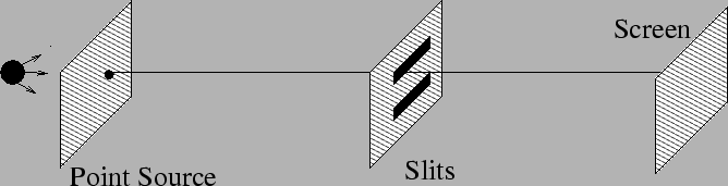 |
Figure 10.1. Light from a distant point source is incident
on a screen with two thin slits. The separation between the two slits
is  . We are interested in the image of the two slits on a screen
which is at a large distance from the slits. Note that the point
source is aligned with the center of the slits as shown in Figure
10.2. Let us calculate the intensity at a point
. We are interested in the image of the two slits on a screen
which is at a large distance from the slits. Note that the point
source is aligned with the center of the slits as shown in Figure
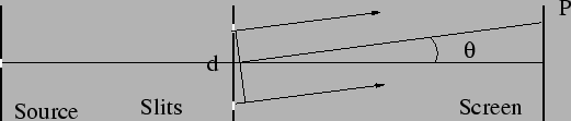
10.2. Let us calculate the intensity at a point  located at an angle
  on the screen.
Figure 10.2:
Young's double slit experiment II
 |
The radiation from the point source is well described by a plane wave
by the time the radiation reaches the slits.
The two slits lie on the same wavefront of this plane
wave, thus the electric field oscillates with the same phase at
both the slits.
If
 and
and
 be the contributions from slits 1 and 2
to the radiation at the point P on the screen, the total electric
field will be
be the contributions from slits 1 and 2
to the radiation at the point P on the screen, the total electric
field will be
 |
(10.1) |
Both waves originate from the same source and they have the same
frequency. We can thus express the electric fields as
 and
and
 .
We then have a relations between the amplitudes
.
We then have a relations between the amplitudes
.
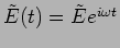
It is often convenient to represent this addition of complex
amplitudes graphically as shown in Figure 10.3.
Each complex amplitude can be represented by a
vector in the complex plane, such a vector is called a phasor.
The sum is now a vector sum of the phasors.
Figure 10.3:
Summation of two phasors
 |
The intensity of the wave is
 |
(10.2) |
where we have dropped the constant of proportionatily in this
relation. It is clear that the square of the length of the resultant
phasor gives the intensity. Geometrically, the resultant intensity  is the square of the vector sum of two vectors of length
  and
and  with angle
  between them as shown in
Figure 10.3. Consequently, the resulting intensity is
between them as shown in
Figure 10.3. Consequently, the resulting intensity is
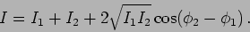 |
(10.3) |
Calculating the intensity algebraically, we see that it is
 |
(10.6) |
The intensity is maximum when the two waves have the same phase
and it is
minimum when
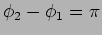 i.e the two waves are exactly
out of phase
i.e the two waves are exactly
out of phase
 |
(10.8) |
The intensity is the sum of the two intensities when the two waves
are  out of phase.
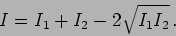
Figure 10.4:
Young double slit interference fringes with intensity profile
 |
In the Young's double slit experiment the waves from the two slits
arrive at P with a time delay because the two waves have to traverse
different paths. The resulting phase difference is
 |
(10.9) |
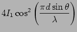
If the two slits are of the same size and are equidistant from the
the original source, then  and the resultant intensity,
For small we have
![\begin{displaymath}
I (\theta) = 2 I_1 \left[ 1 + \cos \left( \frac{2 \pi d \theta } {
\lambda} \right) \right]
\end{displaymath}](img779.png) |
(10.12) |
There will be a pattern of bright and dark lines, referred to as
fringes, that will
be seen on the screen as in Figure 10.4. The fringes are straight lines
parallel to the
slits, and the
spacing between two successive bright fringes is  radians.
Subsections
Next: A different method of
Up: Interference.
Previous: Interference.
Contents
Physics 1st Year
2009-01-06
![$\displaystyle \frac{1}{2} [ \tilde{E}_1 \tilde{E}_1^*+ \tilde{E}_2 \tilde{E}_2^* + \tilde{E}_1 \tilde{E}_2^* +
\tilde{E}^*_1 \tilde{E}_2]$](img767.png)
![$\displaystyle I_1 + I_2 + \frac{1}{2} E_1 E_2 \left[e^{i ( \phi_1 - \phi_2 )} +
e^{i ( \phi_2 - \phi_1 ) } \right]$](img768.png)
![$\displaystyle 2 I_1 \left[ 1 + \cos \left( \frac{2 \pi d \sin \theta } {
\lambda} \right) \right]$](img777.png)