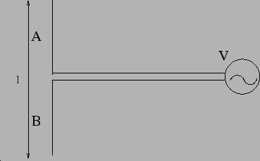
We next consider a situation where a charge accelerates up and down along a straight line. The analysis of this situation using eq. (7.5) has wide applications including many in technology. We consider the device shown in Figure 7.5 which has two wires A and B connected to an oscillating voltage generator. Consider the situation when the terminal of the voltage generator connected to A is positive and the one connected to B is negative. There will be an accumulation of positive charge at the tip of the wire A and negative charge at the tip of B respectively. The electrons rush from B to A when the voltage is reversed. The oscillating voltage causes charge to oscillate up and down the two wire A and B as if they were a single wire. In the situation where the time taken by the electrons to move up and down the wires is much larger than the time taken for light signal to cross the wire, this can be thought of as an oscillating electric dipole. Note that here we have many electrons oscillating up and down the wire. Since all the electrons have the same acceleration, the electric fields that they produce adds up.
The electric field produced is inversely proportional to the distance
![]() from the oscillator. At any time
from the oscillator. At any time ![]() , the electric field is
proportional to the acceleration of the charges at a time
, the electric field is
proportional to the acceleration of the charges at a time ![]() in
the past.
in
the past.
It is possible to measure the radiation using a another electric dipole oscillator where the voltage generator is replaced by a detector, say an oscilloscope. An applied oscillating electric field will give rise to an oscillating current in the wires which can be converted to a voltage and measured. A dipole can measure oscillating electric fields only if the field is parallel to the dipole and not if they are perpendicular. A dipole is quite commonly used as an antenna to receive radio waves which is a form of electromagnetic radiation.
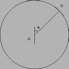
Figure 7.6 shows an experiment where we use a dipole with
a detector (D) to measure the electromagnetic radiation produced by
another oscillating electric dipole (G). The detected voltage is
maximum at
![]() and falls as
and falls as ![]() in other
directions. At any point on the circle, the direction of the
electric field vector of the emitted radiation is along the tangent.
Often we find that placing the antenna of a transistor radio in a particular
orientation improves the reception. This is roughly aligning the antenna
with the incoming radiation which was transmitted by a transmitter.
in other
directions. At any point on the circle, the direction of the
electric field vector of the emitted radiation is along the tangent.
Often we find that placing the antenna of a transistor radio in a particular
orientation improves the reception. This is roughly aligning the antenna
with the incoming radiation which was transmitted by a transmitter.